Skip to content
formulatrix-logo

ROCK IMAGER V4.1

  • What’s New in ROCK IMAGER v4.1
  • Release Notes
  • Hardware Overview
  • System Requirements
  • Best Practices
  • Software Overview
    • Settings Menu
    • Tools Menu
    • Temperature Menu
    • Schedule Menu
    • Plate Menu
    • Status Bar
    • System Overview
    • Imager Menu
      • Focus Graph Sub-menu
      • Drop Location Sub-menu
      • EFI Sub-menu
      • Live Image Sub-menu
      • Imager Menu
      • Live Image Sub-menu
        • Leveling Histogram
        • Optics and Camera Control Panel
        • Well Control Panel
    • Plate Setup Menu
      • Applying Image Masks
      • Tuning Plates in ROCK IMAGER®
      • About Plate Type Calibration
      • Plate Setup Menu
      • Defining Default Imaging Settings
    • Report and Support
      • User Management
      • Licensing
      • Event Log Table
  • Imaging Plates
    • Concepts
      • ROCK IMAGER Processor (RIP)
      • Multi-Fluorescence Imaging (Optional)
      • Single Light Path (Optional)
      • Visible Light Imaging
      • Manual and Automatic Imaging Modes
      • UV Imaging (Optional)
        • UV FAQs
        • UV Compatible Plates
        • UV Light Path
        • UV Absorption Imaging
        • UV Imaging (Optional)
    • Tutorials
      • Searching for Plate
      • Viewing a Plate’s Content
      • Adding and Removing Plates
      • Initiating an On-Demand Imaging Session
  • Home
  • Docs
  • ROCK IMAGER®
  • ROCK IMAGER V4.1
  • Imaging Plates
  • Concepts
  • UV Imaging (Optional)
  • UV Light Path

UV Light Path

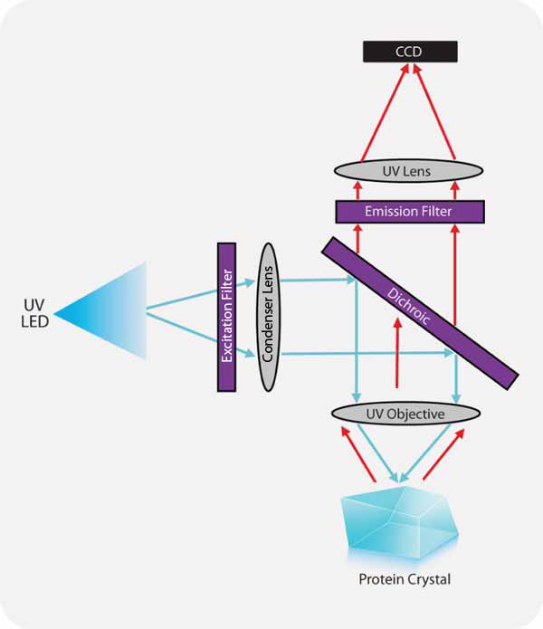
The UV light path is best explained with a diagram.

  • The excitation light is projected onto the protein crystal via the condenser lens - dichroic - UV objective optical chain. (Blue arrow)
  • The tryptophan amino acid flouresces under the UV illumination. (Red arrow)
  • The emission light passes through the UV objective, dichroic, emission filter, and is focused on the CCD sensor by a UV relay lens.

Key: Blue lines indicate excitation light, red lines indicate emission light.

The Diagram of How UV Imaging Works

The Diagram of How UV Imaging Works


Related Topics

  • UV Imaging (Optional)
  • UV Absorption Imaging
  • UV Compatible Plates
ROCK IMAGER 4.1
Updated on June 7, 2024

FORMULATRIX® is proudly powered by WordPress
Scroll To Top