About Plate Type Calibration
During initial hardware installation, FORMULATRIX technicians tune the settings for each plate type you plan to use with your ROCK IMAGER®. However, if you start using new plate types or your imager isn’t capturing drop images as precisely anymore, you may want to fine-tune your plate settings in order to improve drop location accuracy using the Plate Type Calibration feature in the Plate Setup menu. We recommend that only advanced users modify these settings. The information below is for lab managers, so that they may adjust settings as they see fit.
Using Plate Type Calibration
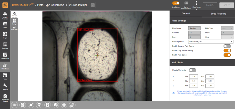
The Plate Type Calibration sub-menu consists of two panels on the right side of the screen: General and Drop Positions.
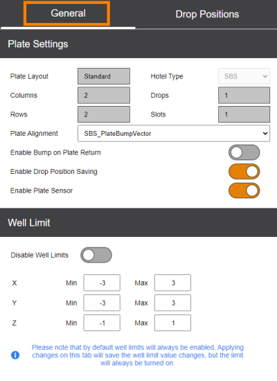
The General panel includes basic information about the specifications of the plate and well limit settings.
Plate Settings | The first three rows are uneditable fields that provide information (obtained from ROCK MAKER) about plate specifications, including the number of Columns, Rows, Hotel Type, Drops per well, and the number of hotel slots required for the plat
Note: For LCP plates, we recommend that you disable this option because this plate type cannot be detected by the sensors, which might cause errors when it’s sent for imaging. |
Well Limits | Contains settings for the limits (in mm) imposed on the robot arm movement as it relates to the well position on the plate. These values will affect how far the imager arm can move along the X, Y, and Z axes when you navigate around a drop using the Fine Tuning Movement controls in the Well Control panel. We recommend that you enable this option. Note: When using plates with larger wells (such as Linbro), increase the X and Y values accordingly so that the drop will not appear off-centered. |
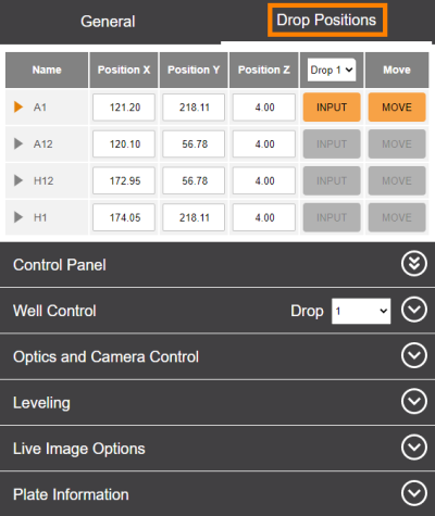
The coordinates in the Drop Positions panel correlate to the corner drops on the plate. From the coordinates of these corner positions, the system uses linear interpolation to compute the locations of all drops on the plate. You can tune these positions for better images at any time.
In this panel, the same Control Panel options that you find in the Live Image sub-menu are also present to help you easily find the precise drop location positions when tuning plates.
FORMULATRIX® is proudly powered by WordPress


